Introduction
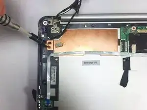
This guide contains numerous steps and will require an extensive amount of time. You'll need access to a T5 Torx screwdriver to complete this process. Make sure your device is unplugged and turned off to proceed with the guide.
Tools
-
-
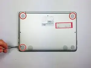
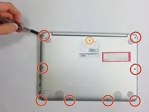
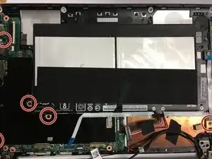
Remove the nine bottom cover screws using a T5 screwdriver. Set apart the 6mm screw in the rear middle of the bottom cover from the the other eight 3mm screws, as it is longer than them.
-
Set apart the 6mm screw in the rear middle of the bottom cover from the the other eight 3mm screws, as it is longer than them
-
-
-
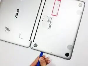
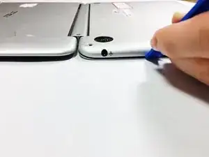
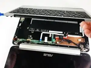
Pry the palm rest assembly apart from the bottom cover using a spudger. This step may require extra power. Once the palm rest has been separated from the bottom cover, pull it away from the screen, rather than away from yourself.
-
-
-
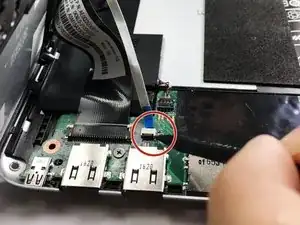
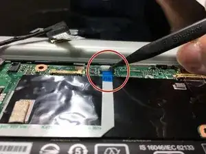
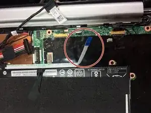
Disconnect the touchpad cable and the keyboard cable on the palm rest assembly from the motherboard using the pointed end of a plastic spudger.
-
-
-
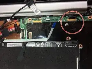
Disconnect the motherboard to powerboard cable from the motherboard using the pointed end of a plastic spudger.
-
-
-
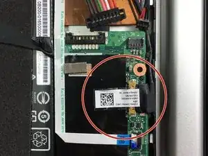
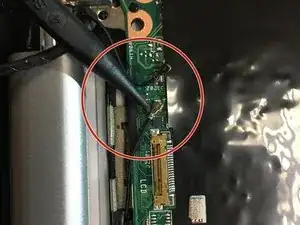
Disconnect the digitizer board cable from the motherboard using the pointed end of a plastic spudger.
-
-
-
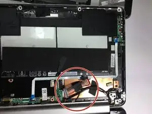
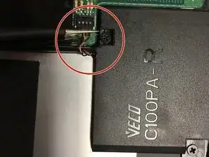
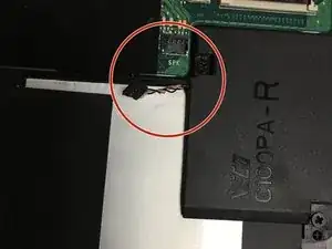
Disconnect the two WiFi antenna cables from the motherboard using the pointed end of a plastic spudger or simply by pulling the cables apart from the motherboard with your fingers.
-
-
-
Disconnect the speaker cable from the motherboard using the pointed end of a plastic spudger.
-
-
-
Remove the four 4.2mm speaker screws, then remove the two speakers using a philips head screwdriver.
-
-
-
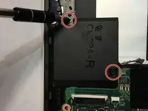
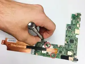
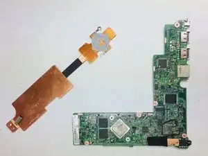
Remove the two 2.7mm heat sink screws with a T5 screwdriver, then remove the heat sink from the motherboard.
-
To reassemble your device, follow these instructions in reverse order.

