Introduction
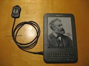
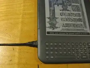
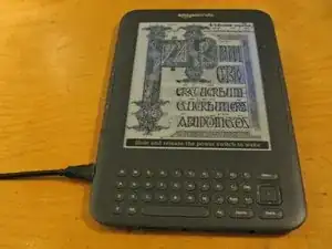
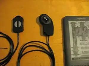
This guide will show you how to add a small pendent type switch to your Kindle 3 so that you can turn the pages without having to hold the device. It should be helpful to someone who might be disabled and has troubled holding the edges. Or just anyone wanting to read in bed while keeping their hands warm under the covers.
It makes use of one of the external side connectors originally designed to supply power to a lighted case/cover. I do not have one to test, but they should be able to be modified to be compatible with this mod.
Tools
Parts
-
-
First you will disassemble you Kindle. Since we will be working exclusively on the back side, Left and Right mean as seen from the back.
-
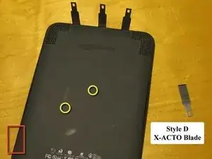
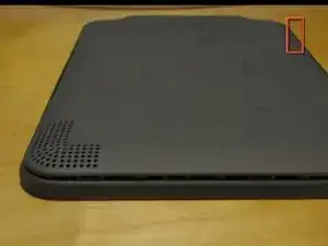
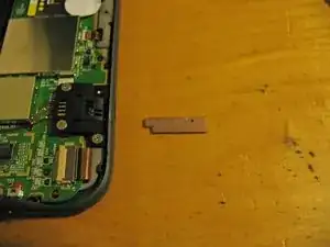
The back is held on by tabs all around the edge and two in the center. I used several type D X-ACTO blades but other spudgers may also work.
-
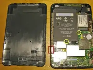
Note: Be very careful when working the spudger around the lower left corner (as noted by the red square). The flex circuit connector for the display is very close to the edge. The keyboard connection is on the lower right side but it is a bit more protected.
-
Once you get the edges unclipped, the back can be slid down slightly to release the inner tabs (Yellow) near the center if they haven't popped out already.
-
-
-
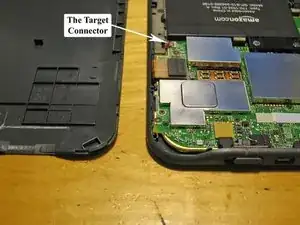
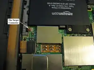
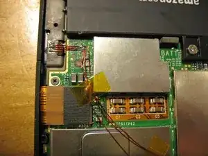
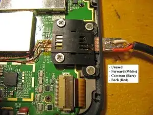
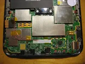
Here is the flex connector that will be soldering to. The other side is closer to the external connector, however there is very little room between it and one of the RFI shields.
-
-
-
Here is where this guide earns it's 'Very Difficult' rating.
-
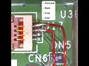
These pictures where taken with a Celestron Deluxe Handheld Digital Microscope. And that's 26 AWG magnet wire.
-
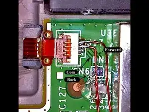
The first picture shows the pinout on the connector. I have labeled the traces on the second picture in case you want to tap them instead. It might be easier.
-
The third picture shows the second time I tried this mod and bridged 2 of the connector pins. I couldn't clear it up and attempting to remove the connector led to it's accidental destruction.
I probably could have gotten a replacement connector butI just folded back the flex cable onto a piece of double sided tape and soldered right to the traces. The original side switches work fine this way, but it's not quite as neat a job as I would have liked. -
The third time, I ended up using 35 AWG magnet wire. I tried first with the larger wire, but messed up the connector again and it had to be removed. After that, I was still having trouble soldering to the pads on the PCB but the smaller wire solved that. The 26 AWG is actually wider than the gap between the pins on the connector and this is probably what caused all the trouble.
-
Update: I haven't found the exact connector, but I did find a compatible one at Mouser. It's a .5mm 4 pin Hirose FPC connector (Mouser Part Number 798-FH34S-4S-0.5SH50)
-
-
-
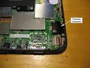
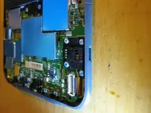
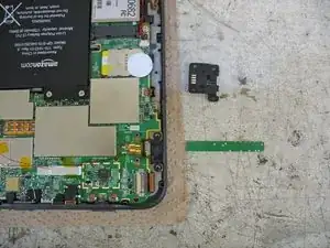
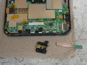
Here is the external connector to be rewired. It's attached with 4 #00 JIS screws and is not soldered to the pads on the logic board.
-
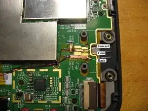
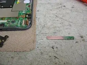
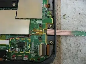
Rather than cutting traces and connecting directly to the pads, I covered them with a piece of Kapton and made new 'pads' with two strips of copper tape. There is a little IC that you will need to run over, but this step is very easy (and reversible).
-
-
-
The next step will be to make the edge connector out of a scrap piece of PCB.
-
I chose a section with ground plane on at least one side. It was sanded down to fit and scored to make 4 'traces'.
-
The size of the traces almost matches a PCI connector. You might be able to scavenge a section from an old card. However, the traces leading away from the edge must travel straight together for a while so you have enough room for the cable for connect to them.
-
I've ordered a prototype connector from BatchPCB and will make it available on their market place once I verify that it works. -
Update: You can now get the connector here from BatchPCB. It's $2.50 but there is a $10 per order set up charge from them so you might also want to order the PCB for the switch at the same time.
-
-
-
The second picture shows the finished edge connector. (It happened to have a via in exactly the wrong place that had to be drilled out.)
-
The third shows the wire soldered on with the pinout I used. A stereo extension cable made the perfect donor. Shield is obviously com, and Red can be Reverse.
-
-
-
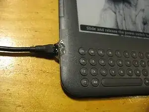
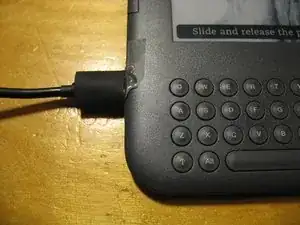
Finishing off the connector with heat shrink and hot glue.
-
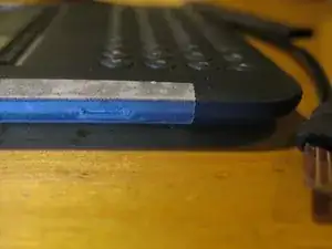
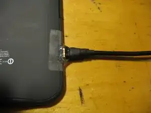
I first covered the hole with a piece of scotch tape with a slot cut in it. The connector is pushed through and hot glue is applied around the connector so it conforms to the outside of the Kindle.
-
The tape prevents the glue from sticking to the Kindle and allows you to remove the connector.
-
-
-
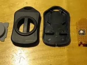
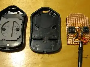
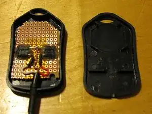
Pretty much any switch will work here. I used a small enclosure by BUD Industries (from Mouser)
-
I made 2 holes in some perf board for a couple of tact switches. They have a nice feel to them.
-
I've ordered a prototype PCB for this enclosure from BatchPCB and will make it available on their market place once I verify that it works. -
Update: You can now get a PCB for the enclosure for 5.00$ There is a 10$ per order set up charge from them so you might also want to order the connector PCB at the same time.
-
-
-
You can now reassemble your Kindle. It's fairly easy, but remember the tabs in the center. Try to engage them first, then go around the edges.
-
The 3rd picture shows an second style of remote using an (ON)-OFF-(ON) rocker switch.
-
4 comments
Why not use the headphone jack? Nobody uses that thing anyways.
Biff -
@Biff hehe ... I use the headphone jack, however, as does my partner. She, for Audible/Kindle audiobooks, and me, when I use the text-to-speech function. : ) Though it would be nice to be able to have headphones do the same thing without all the difficult work. : )
How did you do this?
Rama -
Great, original idea and good execution!
(I didn't even know there was a connector hidden in there before today.)
