Introduction

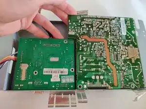
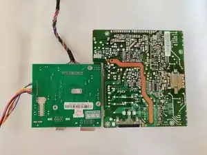
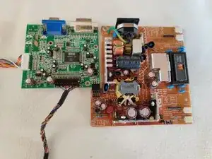
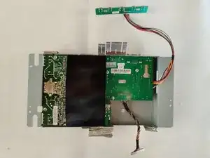
Prerequisite only guide. How to separate the logic and power boards from the metal protective shield.

  1. dr4IdL4rBxuOLdku
    dr4IdL4rBxuOLdku
    baHHjgdK6MgMHX5Y
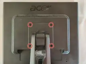
    • Lay the monitor on a flat surface, facedown.

    • Use a #1 Phillips screwdriver to remove the 4x 10.2mm screws securing the stand to the back panel.

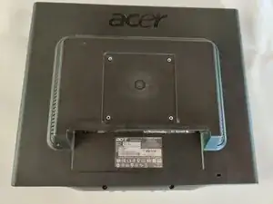
    • Remove the stand from the back panel by pulling it up.

  2. BOG5prMWjTFTSGuP
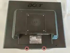
    • Remove the 2x 9.8mm Phillips #1 screws securing the back cover to the monitor.

  3. gYxFLYnlrsFTBvrS
    gYxFLYnlrsFTBvrS
    Y5mioWatAGpoO3cb
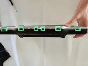
    • Work your way around the monitor, putting the flathead screwdriver into the space between the front and back covers, and prying up.

    • Twisting the screwdriver can help, but you can easily mess up the plastic without getting anything out of it by doing so. Be cautious.

    • Ideally you want to pry at the locations that have the little gaps, which are locking mechanisms.

    • You should hear a poping sound and the back cover should lift a little if you are prying at the right locations.

  4. aGK1iO41lX4bvCcU
    aGK1iO41lX4bvCcU
    STIIVDTWYSoDgHNG
    EXUKsaHXnGX4MVG4
    • I've highlighted the locations of the locking mechanisms for the back cover, try prying in these locations for the best results.

    • Right side of the monitor.

    • Top of the monitor.

    • Left side of the monitor.

  5. 3ECuReFVT1UmV5Mq
    • On the bottom side, be careful not to pry on the monitor buttons.

    • Bottom of the monitor locking mechanism locations.

  6. QREaKT6nTjF4Uqxw
    QREaKT6nTjF4Uqxw
    fNNoPh2LBijTLU3l
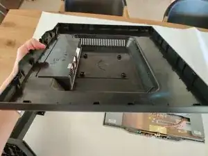
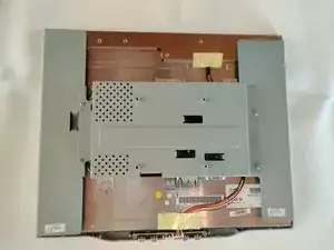
    • The monitor back cover will then pull right off.

  7. tkEPLHGAbiyfjBAN
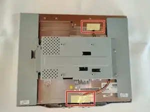
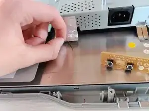
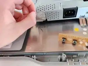
    • Remove the 2 pieces of yellow tape.

    • The bottom one have a thin sheet a metal on the underside which you need to take off too, if it does not come off with the tape.

  8. eCHWhAF6pn1kfHt1
    eCHWhAF6pn1kfHt1
    mMIiLg6wZCxhKB4f
    XQvYRyxdLAr2Lwh4
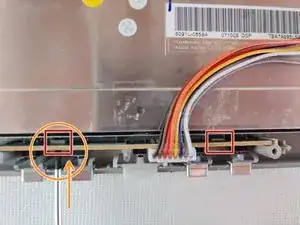
    • The button board is secured to the front frame by 2 plastic locking mechanisms.

    • To remove, insert a Flathead screwdriver into the gap to push the locking mechanism back a little, while pulling up on the board.

    • I found it easier to do one side at a time.

  9. BVscQEoA6LRmclCs
    BVscQEoA6LRmclCs
    mAFsAN1msjxXsKSo
    iXk2ZmGlU4jEBF1M
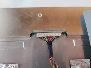
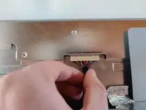
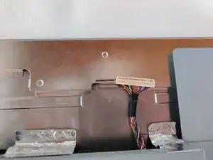
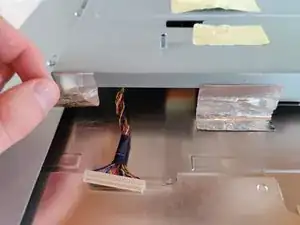
    • Remove the bundled cable connector that is going to the top of the monitor. Grab the black tape that holds all the individual wires together, and pull gently.

    • Be careful to pull evenly on all the wires. You can do this by pulling strait out and not at an angle. Jiggling a little bit can help, but be careful.

  10. LGCVhJRKgxlUoKRH
    LGCVhJRKgxlUoKRH
    ZWkgnTRWVFFCaYEN
    ZownXgHkI1TmPNw3
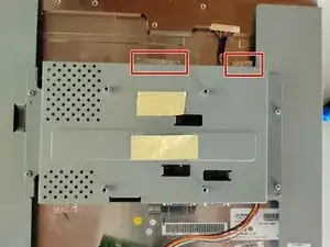
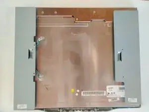
    • Remove the bottom foil tape from the back of the LCD.

    • Be sure to keep it. It helps dissipate static to the ground while the screen is in use. I recommend leaving the side of the tape that is sticking to the shield, where it is.

  11. bcvXQ2nhAZTJZNth
    bcvXQ2nhAZTJZNth
    DKXmgJ4mjLpaQVDS
    AUmIMWv4cLdOrqEZ
    • Remove the remaining 2 pieces of foil tape from the back of the LCD.

    • Keep the pieces of foil tape. They help dissipate static to the ground while the monitor is being used. I recommend leaving on side stuck on the shield.

  12. 2adpnaqowv3Y6Il3
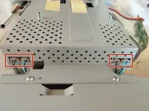
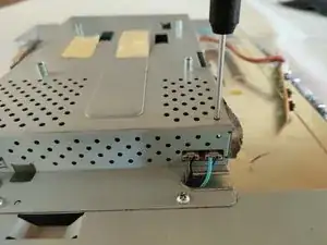
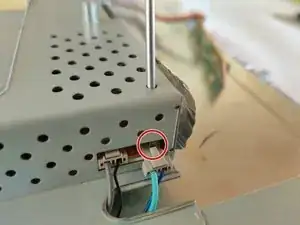
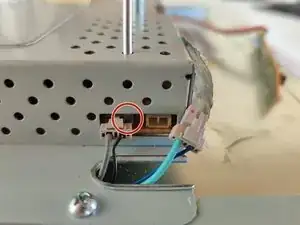
    • Remove the 4 connectors that bring power from the powerboard to the LCD.

    • The connectors have a plastic locking tab on them, and the available space make them very difficult to pull out.

    • Next step shows one way to remove them without too much trouble.

  13. LLQBCSYkTyYsRMYs
    LLQBCSYkTyYsRMYs
    dDnNMo5iqDcHclrx
    gQra5KZYwJYLugEI
    • Insert a Flathead screwdriver into the holes on the top of the shield. Lodge the tip between the socket and the connector and slowly push the connector out of it's socket.

    • Be very careful that you are NOT pushing on the socket itself, but the connector, ideally on the locking tab.

  14. BencRilBfkUqvhCj
    BencRilBfkUqvhCj
    wDYYyOFApYwbtxNk
    xrbLpM4siCP51aUV
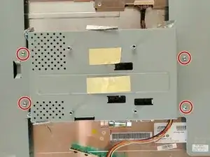
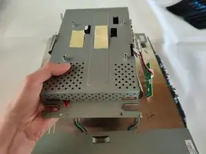
    • Use a Phillips #1 to remove the 4x 8.5mm screws that are securing the shield to the display assembly.

    • Pull the shield up carefully.

    • The power board and logic board are inside the shield.

  15. oiOIcwoyJNxdsis4
    oiOIcwoyJNxdsis4
    UgYZqSCFH2ouCdFP
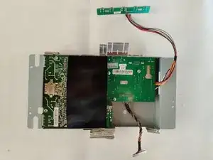
    • Remove the black piece of plastic.

    • Power board is left, logic board is right.

  16. pRdIhiC5ffaUa26K
    pRdIhiC5ffaUa26K
    lvGNqPKLg4afSIiq
    ntsXSbXonK51XTQi
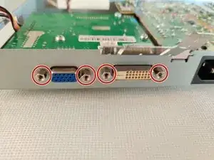
    • Use a 5mm nut driver to remove the 4 hex coupling screws that hold the VGA and DVI sockets to the shield.

    • In a pinch a pair of pliers can be used instead of the 5mm nut driver to remove them.

  17. DUOSHUkg4voZvN3l
    DUOSHUkg4voZvN3l
    geXPPlmN4bBqgnaG
    • Use a Phillips #1 screwdriver to remove:

    • 3x 8.4mm screws holding the logic board down.

    • 3x 8.4mm screws holding the power board down.

    • The last screw holding the power board down is a 10mm screw with some kind of contact washer on it.

  18. JUrFOJcqMicsOiDX
    JUrFOJcqMicsOiDX
    vGlaiAsUkAqPLHVv
    • Lift up the logic and power boards at the same time, just enough to slide them backwards out of the shield.

    • The logic and power boards are connected with a rigid connection, so it is important to lift them both at the same time.

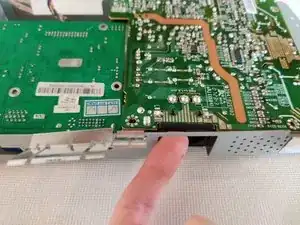
    • You may need to use a finger and push the power socket a bit.

  19. yQIxuOcY2OY2xJku
    yQIxuOcY2OY2xJku
    QmYPeUgJL4LxUVj2
    tXpqSGuPDguvegkv
    • Try not to loose the 2 metal frames that were around the VGA and DVI sockets.

    • Although the power has long been disconnected be careful what you touch on the power board. There are some high voltage capacitors (e.g. 400v), and though they should be discharged, you don't want to take any unnecessary risks.

Conclusion

To reassemble your device, follow these instructions in reverse order.
Sam

Member since: 13/09/14

890 Reputation

0 comments