Introduction
Tools
Parts
-
-
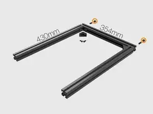
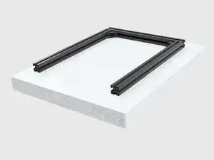
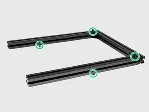
Align aluminium extrusions as seen in the picture. 2 x M8 socket cap screws for top corners of the X frame. Do not full tighten them yet. Just to keep the frame in shape. (Do not forget to insert the T-Nuts before tightening M8)
-
2 x T-Nuts for every corner.
-
Black metal L brackets for each corner.
-
2 x M6 socket cap screws for each corner.
-
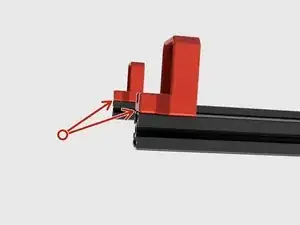
Insert 2 x T-Nuts to the top extrusion as seen in the picture in order to be able to mount the spool holder later.
-
-
-
Insert 2 T-Nuts in front and 2 T-Nuts in back. Position of the screws is not important at the moment. Slightly tighten with M6x14 screws just to keep them in place.
-
Printed Z motor holders should be mounted directional. Smooth rod holes should be positioned on sides as seen in the picture.
-
Insert 2 more T-nuts and mount 2 x Printed Z motor holders
-
Align the Z motor holders with the extrusion ends and tighten the M6x14 socket cap screws.
-
-
-
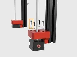
Insert and seat the Z motors into the Z motor holders.
-
Use 4 x M3x10 screws and 4 x M3 Washers to mount each motor in it's place.
-
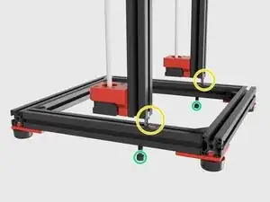
Insert the blind L brackets to Z frame extrusions.
-
Attach M8x40 screws but do not fully tighten them.
-
To reassemble your device, follow these instructions in reverse order.
4 comments
With L brackets, there is no space to route the motor cables
If you are talking about the blind L brackets cables won’t go through that channel. If the L brackets that you mention is the ones at the corners under the feet, cables will go over the brackets. I will share some real pictures for cable managment instead of rendered ones.
The “misumi L brackets” between Z frame and Y beams. Looks like the original MK3 guide tells you to route the Z motors cables through the channel underneath the Z beams, around M8 bolt. In this build, I guess the only option is routing Z motor cables on the inside of the frame.
Yes, what I suggest is walk the cables through the extrusion channel at the bottom. Use the Zaribo extrusion channel plugs to keep them in place.
